
What Is CFD? Is It Just FEA, or Something More Complex?
Is CFD just FEA with fluids?
No. CFD and FEA share a lineage, but they solve different classes of problems, and the fluid side is harder in ways that change how a project must be planned.
Both methods divide a geometry into small cells and solve governing equations numerically. That surface similarity leads many teams to treat CFD as FEA with a different material card. It is not.
A structure carries load through a solid that stays where it is. A fluid carries momentum, heat and mass while it moves, and its motion feeds back into the equations that describe it.
That feedback is where the complexity begins.
What CFD actually is
Computational Fluid Dynamics (CFD) is the numerical solution of the equations that govern fluid flow, heat transfer and related transport phenomena.
Closed-form solutions exist only for a handful of idealized cases. A CFD solver instead divides the fluid domain into a mesh of small cells, computes velocity, pressure and temperature in each one, and iterates until the whole field is self-consistent.
The questions it answers are the ones physical testing makes slow or expensive:
- Pressure drop across a valve, manifold or heat exchanger
- Lift, drag and stability of a body moving through air or water
- Temperature distribution in electronics enclosures and cooling channels
- Mixing, residence time and species distribution in reactors
- Flow through biomedical geometries such as arteries, stents and airways
The result is a full field of data, not a single reading. Engineers see where a flow separates, where a surface overheats and where a design wastes energy, before any prototype is built.
The three equations behind every CFD solver
Every CFD solver, commercial or open source, rests on three conservation laws: mass, momentum and energy. Turbulence models, boundary conditions and numerical schemes all exist to close or constrain these equations.
- Continuity (conservation of mass). Mass entering a control volume must match mass leaving it, plus any accumulation. For incompressible flow the density term drops out and the equation reduces to ∇·v = 0, a constraint on the velocity field.
- Navier-Stokes (conservation of momentum). Newton’s second law for a fluid element. The left side is fluid acceleration, local plus convective. The right side is the sum of forces: pressure gradient, viscous stress and body force such as gravity.
- Energy (conservation of energy). Tracks temperature through convection, conduction, viscous dissipation (Φ) and external heat sources (Q). It is switched on only when thermal behavior matters.
In these equations ρ is density, v velocity, p pressure, μ dynamic viscosity, g gravitational acceleration, C_p specific heat, T temperature, k thermal conductivity, Φ viscous dissipation and Q the external heat source.
The forms shown assume incompressible flow, a Newtonian fluid and constant properties. High-speed gas flow, variable-property fluids and multiphase flow use more general forms with additional terms, and in compressible flow the energy equation couples back to density.
How a CFD simulation works
A CFD study moves through six stages, and the last one decides whether the first five can be trusted.
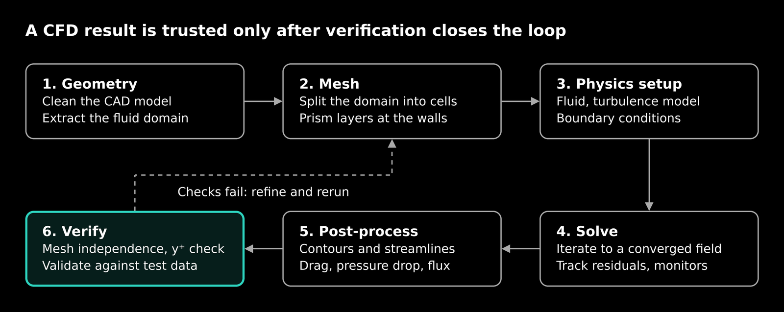
CFD workflow · 6 stages, 1 feedback loop
Stages 1 to 3 define the problem, stage 4 solves it, and stages 5 and 6 turn the field into a decision. A failed check sends the model back to the mesh.
The solver uses the finite volume method. It integrates each conservation equation over every cell, so the mass, momentum and energy leaving one cell equal what enters its neighbor. That keeps the solution conservative, even on a coarse mesh.
Simulations run in one of two modes. A steady-state run seeks a single converged field. A transient run marches forward in time steps and captures vortex shedding, start-up behavior and other effects that change with time.
CFD vs FEA: shared workflow, different physics
CFD and FEA follow the same workflow of geometry, mesh, boundary conditions, solve and verification. Readers who want the structural side in detail can start with our guide to finite element analysis, which walks through that workflow for solids. The two differ in what they solve for and in how difficult that solution is.
| Aspect | CFD | FEA |
| Physical domain | Liquids, gases and convective heat transfer | Solids and structures |
| Primary unknowns | Velocity, pressure, temperature, density | Displacement, then strain and stress |
| Governing equations | Continuity, Navier-Stokes, energy | Equilibrium, constitutive law, compatibility |
| Mathematical character | Nonlinear, often transient, convection-dominated | Often linear; nonlinear with plasticity, contact or large strain |
| Mesh priorities | Fine prism layers at walls, refinement in wakes and shear layers | Refinement at stress concentrations and load paths |
| Dominant discretization | Finite volume (ANSYS Fluent, STAR-CCM+); finite element also used (COMSOL) | Finite element |
| Largest modeling uncertainty | Turbulence model and wall treatment | Material model, contact and constraints |
| Typical outputs | Pressure drop, velocity field, drag, heat flux | Stress, deformation, natural frequency, factor of safety |
Why CFD is the harder problem
CFD is harder than a typical structural analysis because its equations are nonlinear, tightly coupled and, for most real flows, unclosed without a turbulence model.
Nonlinearity. The convective term v·∇v multiplies the unknown velocity by its own gradient. A linear static FEA problem is solved once. A CFD problem is linearized and iterated, and it can settle on different solutions depending on how it starts.
Pressure-velocity coupling. In incompressible flow there is no transport equation for pressure. Pressure acts as a constraint that keeps the velocity field divergence-free, so solvers use algorithms such as SIMPLE or fully coupled schemes to satisfy both together.
Turbulence. Most engineering flows are turbulent, with eddies spanning several orders of magnitude in size. Resolving all of them directly is impractical for industrial geometries. Averaged approaches such as RANS introduce extra unknowns, so the equations need a model (k-ε, k-ω SST) to close them. Large Eddy Simulation resolves the large eddies and models the rest, at a much higher computational cost.
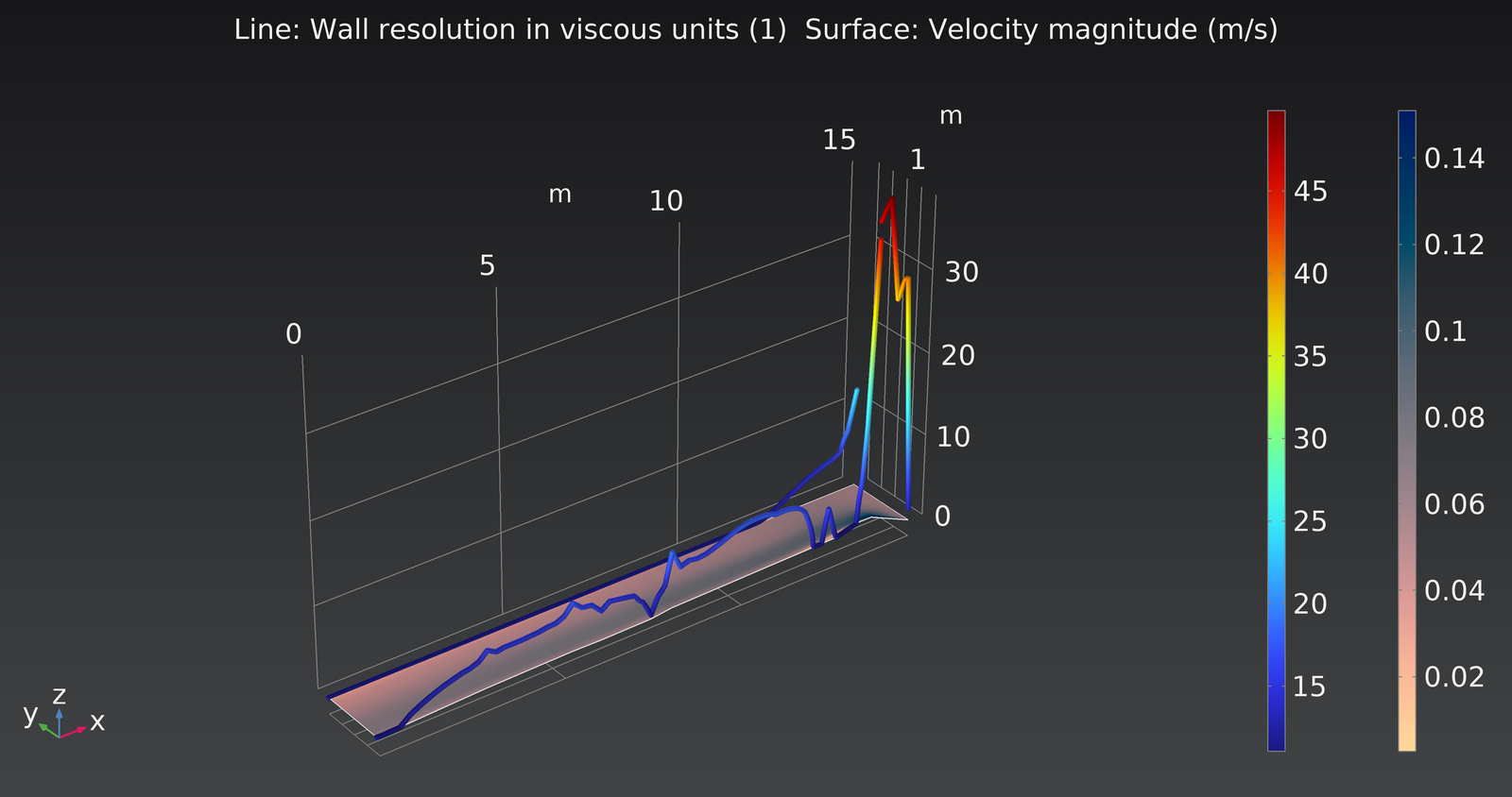
Boundary layers. Drag, heat transfer and separation are decided in a thin region at the wall. The first cell height, expressed as y⁺, must match the wall treatment: near 1 to resolve the viscous sublayer, or roughly 30 to 300 when wall functions are used.
Convergence is not correctness. Falling residuals show that the discretized equations are being satisfied. They do not show that the mesh, the model or the answer is right.
Before trusting a result, engineers check:
- Mesh independence on the quantity that drives the decision
- y⁺ consistent with the chosen wall treatment
- A turbulence model justified for the flow regime
- Stable monitors on integral values such as drag, pressure drop and heat flux, not residuals alone
- Validation against test data or a trusted benchmark
Where CFD and FEA meet
The question “is CFD just FEA?” is partly a category error. The finite element method is a numerical technique. CFD is a discipline defined by the physics it solves.
That is why some tools solve fluid flow with finite elements, while most dedicated CFD codes use the finite volume method, which conserves mass, momentum and energy cell by cell. Different discretization, same governing equations.
In practice the two disciplines are most useful together:
- Conjugate heat transfer. Fluid flow and conduction through solids are solved in one model, for example a heat sink, a battery pack or a turbine blade with internal cooling.
- One-way fluid-structure interaction. CFD pressure and thermal loads are mapped onto a structural model to compute stress and deformation.
- Two-way fluid-structure interaction. The structure deforms enough to change the flow, as in flexible wings, heart valves and vibrating pipework. Both solutions are updated until they agree.
- Multiphysics. Flow coupled with electromagnetics, chemical reactions or phase change, solved on a shared model.
The practical consequence is simple. A structural analysis needs the right loads. A CFD analysis often supplies them.
Closing thoughts
CFD is not FEA with a different material card. It is a separate discipline, built on three nonlinear conservation laws and a turbulence modeling layer that most structural work has no equivalent for.
Three principles hold across every flow problem:
- A mesh is an approximation, not a result.
- A converged solution is not a validated one.
- The physics decides the method, not the software.
At AWJ Engineering, CFD and FEA are applied together in simulation-driven design, so teams reach engineering certainty before they commit to hardware.
Partner With AWJ Engineering for CFD
Our CFD services cover fluid flow, heat transfer and coupled Multiphysics simulation using industry-leading tools like ANSYS Fluent and COMSOL. Whether you need a single design validation or ongoing simulation support across your product line, our team delivers results you can act on with confidence.
Simulation also pairs with AI. Our Agentic AI for Engineering Design & Optimization service builds physics-informed surrogate models that accelerate CFD and FEA runs, and uses generative design and optimization to explore thousands of design variants. Results are validated with physics checks, and the models plug into your existing CAD, FEA and CFD workflow.
Ready to validate your next design? Explore our CFD services or contact AWJ Engineering to discuss your project.
